Guidelines:
Windows DNA Sample Architecture Patterns and Implementation Mechanisms
This material is provided courtesy of Applied Information
Sciences, Inc.

Topics
References 
Designing Component-Based Applications by Mary Kirtland, Microsoft
Press
Building Web Applications Using UML by Jim Conallen, Addison-Wesley
Summary 
These guidelines describe sample logical architectures for Microsoft®
Windows DNA-based applications, and provide a description of the implementation
mechanisms available on the Windows DNA platform. These guidelines also provide
general information on modeling the architecture pattern elements in Rational
Rose.
Applications developed using the Windows DNA platform should be constructed
using a layered architecture approach. The standard logical architecture model
for Windows DNA-based applications is a three-layer model consisting of
presentation, business logic, and data layers as shown in the figure below.

Standard Windows DNA Application Logical Architecture
Layers
As defined in Concepts: Layering,
the number of logical architecture layers that are appropriate for an
application design varies with the overall complexity of the application. The
complexity of the application is measured by the number of classes in the
application and/or the distribution strategy for the application (see Concepts:
Distribution Patterns). When designing Web-based applications using the
Windows DNA platform, the software architect and designer should consider using some or
all of the following architecture layer extensions to the standard three-layer
pattern shown in the sample architecture patterns in the two diagrams below:
- Presentation (with optional thin and thick Web client layers)
- Façade
- Business Logic (with optional External System Interface and Server layers)
- Data Access
- Data
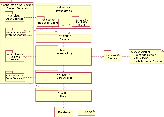
Sample Web Application Logical Architecture Pattern
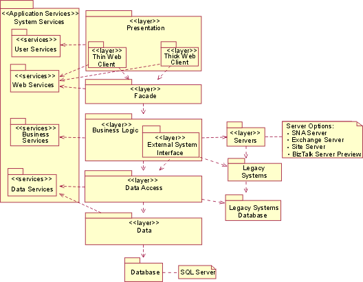
Sample Web Application with External System Interface
Logical Architecture Pattern
The layers depicted in the sample logical architecture patterns are described
in the following sections of these guidelines. The patterns contained in these
guidelines represent only two instances of a wide range of possible architecture
patterns that can be created for the Windows DNA platform. The application
services and servers elements depicted in the sample patterns are described in
the second section of these guidelines, Windows DNA Implementation Mechanisms
Overview.
The sample logical architecture patterns described in these guidelines can be
used in many, different physical deployment architectures. The types of physical
architectures range from a standard two-tier client/server machine
architecture, to an enterprise wide architecture that includes multiple client
machines, Web servers, application servers, data servers, and so on.
The presentation layer of a Windows DNA-based Web application should contain
the Component Object Model+ (COM+) components, and forms, client pages, and
server pages that provide operations to manage the user interaction with the
application. As described in Concepts:
Web Architecture Patterns there are two general patterns that can be viewed
as layers of the presentation layer for Windows DNA Web-based applications: Thin
Web Client and Thick Web Client.
The Thin Web Client layer consists of scripts in the form of Active Server
Pages (ASPs) and COM+ components that are typically located on a server tier
machine. These scripts and components generate Hyper-Text Markup Language (HTML) formatted data
that is sent to the user's client machine and displayed by a browser application
such as Microsoft Internet Explorer, in
response to user requests. The components that comprise the Thin Web Client
layer may utilize the User Services and Web Services implementation mechanisms
provided by the Microsoft Windows Internet Information Services (IIS)® and
Microsoft Internet Explorer®.
The Thick Web Client layer contains COM+ components and/or client side
scripts that are downloaded and invoked on the user's client machine. The Thick
Web Client layer may also be thought of as a “local client business
object” layer.
The façade layer should be used as an “insulator” between the components
in the presentation layer and the business logic layer components. The software architect
should consider the use of a façade layer if there are multiple types of client
interfaces with different levels of functionality, such as the case in which the
application must support Web-based clients and non-Web-based (native) clients.
However, for smaller-scale applications with a single type of client interface,
the façade “layer” components may exist as a subsystem or package contained
entirely in the presentation layer.
The COM+ components in the façade layer act as interpreters that understand
how to translate client specific requests from presentation layer components to
call the appropriate generic business logic component operations. The façade
layer components also translate the data returned by the business logic layer
components into the specific format needed by the presentation layer components.
The façade layer can be thought of as a “business logic access layer”, in
that it performs similar functions as the data access layer in shielding the
business logic components from having to know about the specifics of user data
formats. The complexity and number of components in the façade layer depends
directly upon the complexity of the user interface and the number of different
types of client interfaces that need to be supported.
The business logic layer should contain the components that provide the
critical business functionality for a Windows DNA-based application. One of the
key architectural goals of using an n-layer logical model is to be able to
separate the business components from the details of the environment in which
they operate to enable reuse of the business logic components across different
applications. Business logic components typically make the most use of the
application Business Services provided by the Microsoft Windows® operating
system, including: COM+ queued components, COM+
transaction services, object pooling, loosely coupled events, component security
services and so on.
The COM+ components in the business logic layer can be grouped into different
layers depending upon the complexity and size of the application. For Windows
DNA-based applications, the software architect should consider the use of the following:
- External System Interface Layer
- Servers Layer
This layer contains business logic components that provide operations for
interacting with external applications to provide business-oriented
functionality. In general, the software architect should consider creating a separate
layer package or subsystem in the design and implementation models for each
external system. This partitioning insulates the core business logic components
from potential changes to the interfaces between the application and the
external systems.
This layer contains the business logic components that interact with the
Server products that are part of the Windows DNA platform. Windows DNA Servers
currently include the following products: Microsoft Exchange Server®, Microsoft
Site Server Commerce Edition®, Microsoft SNA Server®, and Microsoft BizTalk
Server® -Technology Preview. It should be noted that Microsoft is currently
planning a major update to the entire Servers product family for the Windows DNA
platform in 2000, and will introduce two new server products: Internet Security
and Acceleration (ISA) Server® 2000 and Application Center Server® 2000. Refer
to the Microsoft Corporation Windows DNA home page (www.microsoft.com/dna)
for the latest information on the Server products.
The Server products expose operations via COM+ interfaces that can be used by
business logic layer components to implement specific business functionality.
The software architect should define a separate layer or subsystem package in the design
and implementation models for each server product used by the application. These
Server product packages will contain the application COM+ components that use
the operations provided by the Servers. This partitioning insulates the core
business logic components from potential changes to the interface operations
that may occur with new releases of the Server products.
The data access layer should consist of COM+ components that provide generic
data access operations to the business logic components. The data access layer
components shield the business logic components from the details of accessing
data from potentially multiple persistent data stores. The components in the
data access layer utilize the Microsoft Data Access Component (MDAC) services
provided with the Microsoft Windows operating system. These services include
ActiveX Data Objects (ADO), OLE DB, and Open Database Connectivity (ODBC), which
are provided as part of the Microsoft Universal Data Access® (UDA) strategy.
See Guidelines: Universal Data Access (UDA) Design for more information on UDA.
The components in the data access layer may also utilize the built-in
eXtensible Markup Language (XML) parser services of the Windows operating
system.
The data layer contains the actual data stores used in the application and
the Server products that manage the physical content and structure of the data
stores. For Windows DNA-based applications, the data layer usually consists of
the Microsoft SQL Server® relational database management system (RDBMS). The
data layer may also contain non-Microsoft database management systems and data
stores.
As defined in Concepts: Analysis Mechanisms and
Concepts: Design and
Implementation Mechanisms, implementation mechanisms are concrete refinements of
analysis and design mechanisms in which a specific vendor technology solution is
applied to a particular problem. The software architect may specify high-level
candidate implementation mechanisms initially during the Workflow Detail:
Perform Architectural Synthesis. The selection of implementation mechanisms
evolves during the Inception and Elaboration phases as the software architect, designer,
user interface designer, and database designer roles define the detailed
analysis and design mechanisms to be used in the development of the application.
The Microsoft Windows DNA platform provides the software architect with the
implementation mechanisms in the form of Application Services included with the
Microsoft Windows platform, and in form of the Microsoft Windows DNA Servers
products. The Windows DNA implementation mechanisms defined in these guidelines
are based upon the initial release of the Microsoft Windows 2000 operating
system.
Application services are core component support functions that are provided
with the Microsoft Windows operating system. Application services expose
interfaces that contain operations that can be accessed using COM+ technology.
The designer and implementer roles can use the pre-defined application
services in the Workflow Detail: Design Components and
Workflow Detail:
Implement Components. The designer may use the interface operations of the COM+
components that provide the Windows application services when designing classes
and components during the Activity: Class
Design and Activity: Subsystem Design. The implementer creates the code to access the application services
during the Activity: Implement Component. Windows DNA application services can
be included in the Artifact: Design Model and
Artifact: Implementation Model
using the Rational Rose Visual Basic Framework. Rational Rose also provides
support for importing COM+ components into the Design and Implementation models.
Refer to the Tool Mentor: Reverse- Engineering
Code Using Rational Rose.
The application services provided in the Microsoft Windows operating system
can be divided into the following five major logical groups:
- User Services
- Web Services
- Business Services
- Data Services
- System Services
User services are built-in support functions that can be used to implement
components that provide user navigation services and display information to the
user either through the Microsoft Internet Explorer browser based user interface
or through a compiled Windows based user interface. User Services include
implementation mechanisms that provide support for rendering HTML and DHTML
formatted data to the user.
Web services are built-in support functions that provide implementation
mechanisms for Web-enabled applications. Web services include the built-in Web
server functions provided by IIS for handling and routing requests for Web
pages. Web services also include built-in functions for creating dynamic web
content using Microsoft’s Active Server Page (ASP) technology.
Business Services are the core component services and business support
functions provided by the Microsoft COM+ infrastructure which includes the
following types of implementation mechanisms:
- COM+ component management services including support for component
registration, object activation, and method call interception and routing.
- Message queue services (formerly packaged for the Windows NT operating
system as Microsoft Message Queue Server® (MSMQ) product). Message queuing
services provide support for COM+ Queued Components.
- COM+ Transaction services (formerly packaged with the Windows NT platform
as the Microsoft Transaction Server® (MTS) server product).
- Application throughput scalability functions including COM+ object pooling
and Compensating Resource Managers (CRMs) services.
- Multi-threading process control services (formerly part of the MTS server
product).
- Component level security services.
- COM+ Loosely Coupled Event (LCE) services.
Data Services include implementation mechanisms for data access support
functions provided by the Microsoft Data Access Components (MDAC). Data services
also include built-in support functions for handling eXtensible Markup Language
(XML) data.
System Services include built-in support functions for inter-process
communications, application and component distribution, load balancing,
application fail-over, operating system-level security, and file/print/directory
management services. These are core operating system capabilities that are
provided as implementation mechanisms via exposed COM+ interfaces. The table
below lists
example System Services implementation mechanisms.
|
Analysis/Design Mechanisms
|
Windows DNA Platform System Services
Implementation Mechanisms
|
|
Inter-Process Communications
|
Distributed COM (DCOM) services
|
|
Application and Component Distribution
|
COM+ Catalog services
|
|
Application File Management
|
Active Directory services
|
|
Scalability
|
Network Load Balancing (NLB)
Windows 2000 Advanced Server®
Windows 2000 Data Center Server®
|
|
Fail-over/Availability
|
Windows Cluster Services
|
|
Application User Authentication
|
Windows 2000 Security Services
|
Example System Services Implementation Mechanisms
The second major set of implementation mechanisms provided by the Microsoft
Windows DNA platform are Servers. Like the application services, Servers provide
component support functions that the designer and implementer can utilize in the
design and implementation of application classes and components. Unlike
application services, servers are not built-in components included with the
Microsoft Windows operating system, but are separate add-on products.
Servers are primarily used as implementation mechanisms for business logic
layer and data access layer components. The designer and implementer roles can
utilize the operations provided in the exposed COM+ component interfaces
provided by the Server products in the design and implementation of application
classes and components. The table below lists example implementation mechanisms provided
by the Windows DNA platform Servers.
|
Analysis/Design Mechanism
|
Windows DNA Platform Server Product* Implementation
Mechanism
|
|
Messaging and Collaboration
|
Exchange Server
|
|
E-Commerce
|
Site Server Commerce Edition
|
|
Mainframe Application Integration
|
SNA Server
|
|
Relational Database Management (RDBMS)
|
SQL Server
|
|
Web-based Electronic Document Interchange (EDI)
|
BizTalk Server
|
Example Server Product Implementation Mechanisms
* For a current list of available server products for the Windows DNA
platform see the Microsoft Corporation main Windows DNA Web site at www.microsoft.com/dna.
As part of the activities in the Workflow Detail: Perform Architectural
Synthesis, the software architect should create packages with the stereotype «layer» in the
Artifact: Design Model for these layers. See the
Tool Mentor: Managing the Design
Model Using Rational Rose for more information on
creating architectural elements in a Rational Rose model.
The software architect may refine the logical layer model as the design of the
application evolves throughout the Inception and Elaboration phases. As the
design of the application is developed in the Workflow Detail: Design
Components, each class and subsystem should be grouped within one of these
logical layer packages in the Design Model. The figure below shows an example of how the
layers are organized in a Rational Rose model.
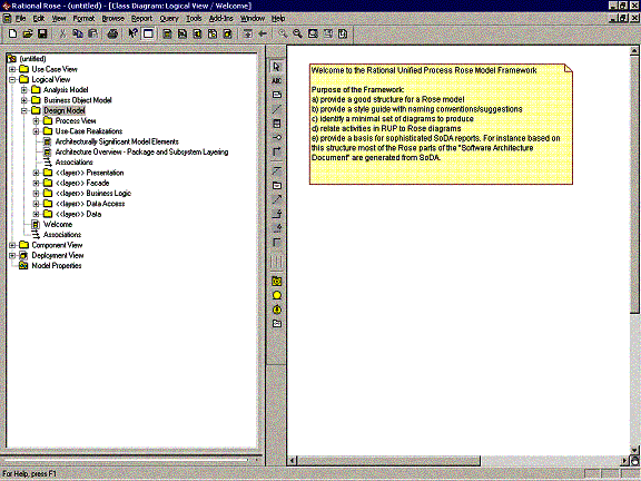
Logical Architecture Layers in the Design Model.
During the Workflow Detail: Structure the Implementation
Model, the software architect
should create the same logical layer packages in the Artifact: Implementation
Model that corresponds to the logical layer packages in the Design Model, as
shown in the figure immediately below. In general, the software architect should group each component to be
contained in the same «layer» package as the subsystem that
corresponds to the component in the Design Model. There may be cases where the
package structure of the implementation model may also need to include
additional application specific packages to model the physical distribution of
the components onto specific server platforms.
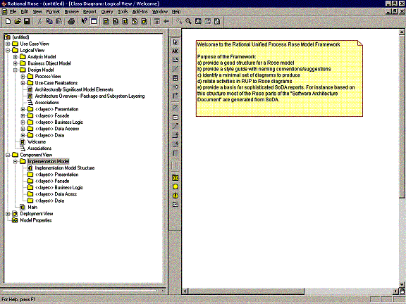
Logical Architecture Layers in the Implementation Model
For Web-based applications, the software architect should consider using packages to
organize the pages, scripts, and COM+ components in the Artifact: Design Model
and Artifact: Implementation Model to differentiate between server side design
elements and client side elements. A sample Design Model package structure is
shown in the figure immediately below, which uses the following packages in the presentation layer:
- Client Classes
- Client Pages
- Forms
- Server Classes
- Server Pages
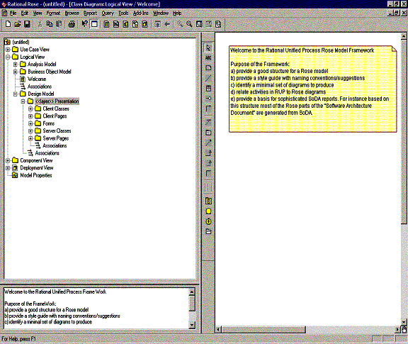
Sample Design Model Presentation Layer Organization
The Client Classes package is used to contain the design classes that will be
included in COM+ components, which are downloaded to the user’s machine, in
order to provide enhanced UI functionality and limited business logic
processing.
The Client Pages package contains the design classes that represent the ASP
pages that will be generated by server side components and transferred to the
user’s client machine. The Client Pages package also includes client side
scripts that are downloaded to, and operate on, the user’s client machine.
The Forms package contains any design classes that model Web forms that are
included as part of the user interface of the application.
The Server Classes package should contain the presentation layer design
classes that reside on the server side of the application presentation layer.
The Server Pages package should contain the server side ASP pages that provide
UI operations, including the generation of client side pages.
In the Implementation Model, the software architect should consider using the same
presentation layer package structure to organize the COM+ components and ASP
pages, to separate out the client side components and scripts from the server
side components and scripts.
Rational Rose provides the ability to reverse engineer the design of a
Windows DNA-based Web application and reverse engineer the design of SQL Server
Databases. See the Rational Rose on-line help topics, “Rose Web Modeler” and
“Rose Data Modeler”, for detailed information on the reverse engineering
process.
The Web application reverse engineering process creates two Web site
Packages,
one in the Logical View and one in the Component Views of the Rose model. The
Logical View Web site package contains the class diagrams that depict the
interaction between the COM+ components, server side ASP pages, and client side
ASP pages.
The Component View Web site Package contains model elements for each ASP page
reverse engineered from the Windows DNA-based web application. The Web site package does not distinguish between client side and server side model elements.
Since the Web site packages represent the implemented structure of the
application, the software architect should not include new or modified design elements in
the Web site packages. The software architect should use the presentation layer package
structure described above to maintain logical separation between new design
elements for the application and the existing application structure.
Copyright
© 1987 - 2001 Rational Software Corporation
|  Artifacts >
 Analysis & Design Artifact Set >
 Software Architecture Document >
 Guidelines >
 Windows DNA Sample Architecture Patterns and Implementation Mechanisms
 Artifacts >
 Analysis & Design Artifact Set >
 Software Architecture Document >
 Guidelines >
 Windows DNA Sample Architecture Patterns and Implementation Mechanisms


![]()